The ESP32-C3 receives joystick data via ESP-NOW and needs to transmit motor commands to the STM32L432KC motor control board. Simple enough in concept—SPI communication between microcontrollers handles this interface. The reality involved learning SPI fundamentals, implementing interrupt service routines, debugging timing discrepancies between logic analyzers and software logs, and discovering the critical importance of proper ISR design in embedded systems.
Learning SPI from Fundamentals
The journey began with understanding what SPI actually is. Re-reading chapters from “Making Embedded Systems” by Elicia White provided the theoretical foundation, but implementing it on the ESP32-C3 required reverse engineering existing code examples.
An OLED tutorial provided the starting point—working SPI code that could be dissected and understood. This exploration led to implementing the first interrupt service routine (ISR) for the project, a milestone that opened understanding of hardware-driven event handling.
ESP32-C3 SPI Implementation Discovery
The ESP32-C3’s SPI implementation proved more complex than basic SPI theory suggested. Converting from C++ to C reduced ROM footprint—a lesson learned from the OTA project where unused libraries consumed significant memory space.
Understanding the chip select (~CS) pin behavior became crucial. Unlike SCLK, MISO, and MOSI pins that have specialized SPI functions, ~CS operates as a standard GPIO pin under software control. This revelation explained much about SPI transaction management.
Hardware Interface Reality
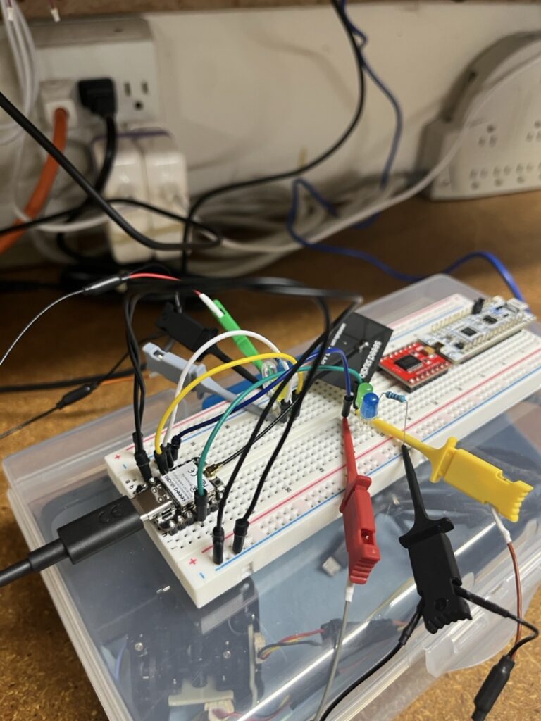
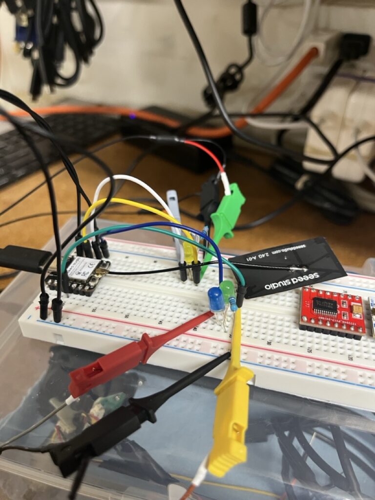
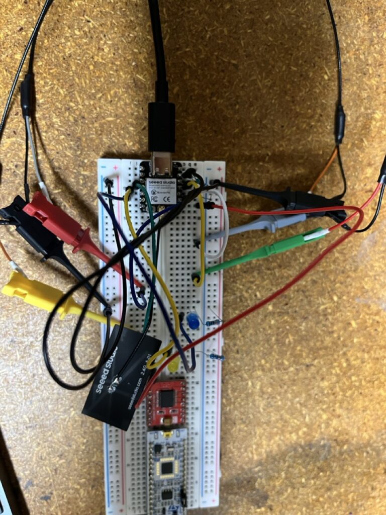
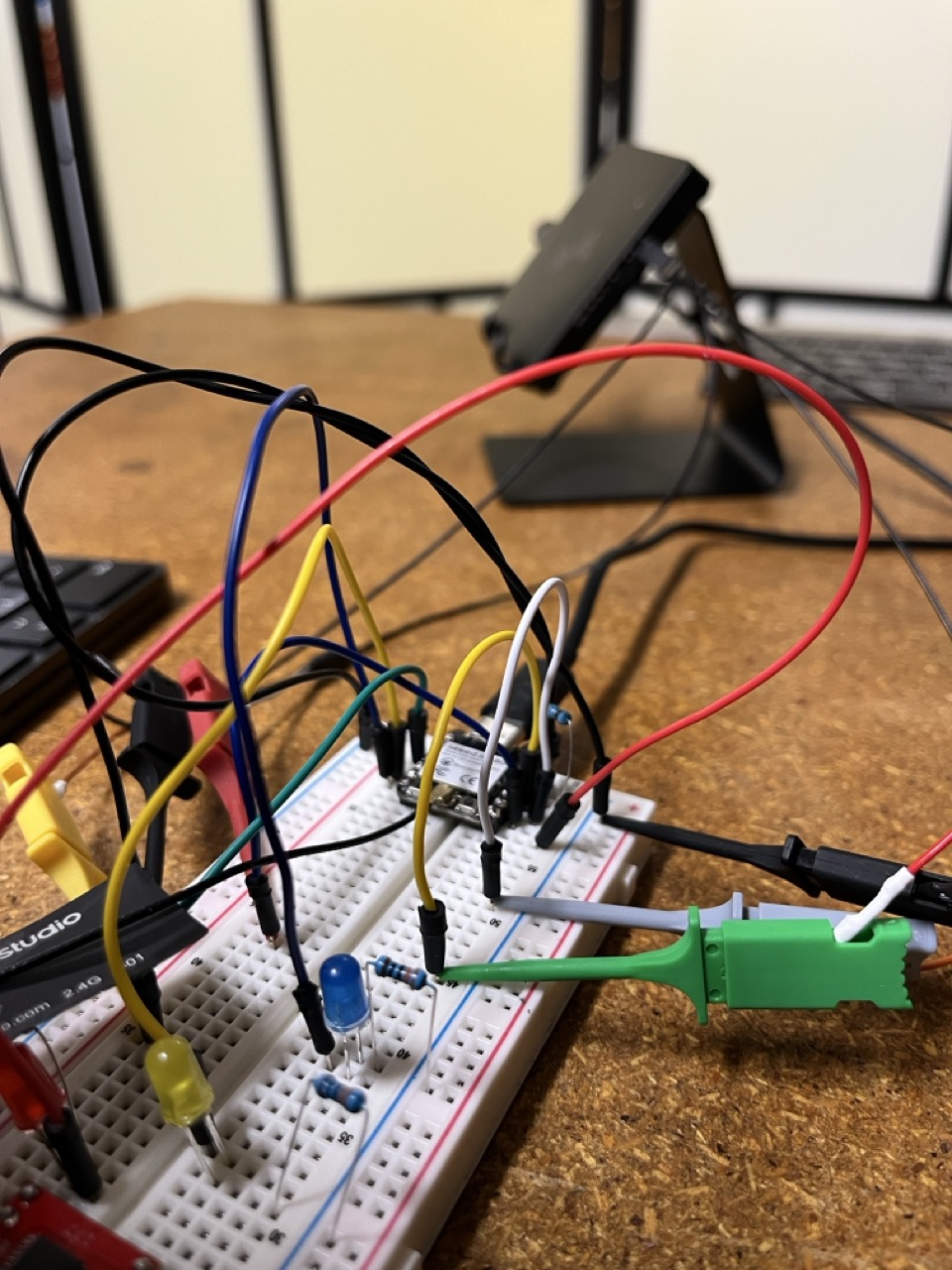
Implementing physical SPI communication required understanding pull-up and pull-down resistors. A simple button interface for testing SPI functionality introduced these concepts practically—buttons need proper electrical termination to function reliably.
Success came gradually. An LED controlled via SPI and ISR provided the first evidence that SPI transactions were occurring. The LED blinked in response to SPI activity, confirming that the interrupt system was triggering correctly.
Development Environment Decisions
Initial attempts used pure CMake for ESP32-C3 development, aiming for maximum control over the build process. However, the complexity of ESP32-C3’s hardware abstraction and peripheral drivers made esp-idf the pragmatic choice for forward progress.
This decision eliminated the need for OpenOCD and GDB debugging, though it meant sacrificing the low-level control and visibility those tools provide. The aspiration to move away from esp-idf remains, but development velocity took priority.
Protocol Verification and Debugging
Logic analyzer verification provided the first definitive proof that SPI was working correctly. Visual confirmation of clock signals, data transitions, and timing relationships gave confidence that the implementation was fundamentally sound.
However, confidence wasn’t complete. Understanding exactly what was happening required deeper investigation, but the logic analyzer confirmed that data was flowing and the ISR was responding to SPI events appropriately.
Further testing at 1MHz sampling on the logic analyzer revealed consistent data patterns responding to test inputs. The breakthrough came when ASCII data became visible in the logic analyzer traces—’LIGHT_ON’ messages appeared clearly, confirming end-to-end communication.
A timing discrepancy emerged between logic analyzer captures and ESP_LOG output. The hardware showed one timing pattern while software logs suggested different behavior. This inconsistency demanded resolution before proceeding to STM32 integration.
Transmitter Development and FreeRTOS Discovery
The transmitter (TX) side required attention to resolve timing issues. Converting from C++ to C and implementing the same esp-idf workflow used for the receiver provided consistency across the communication system.
The TX implementation used binary semaphores—a pattern that triggered recognition from university training that there might be better synchronization mechanisms available. The ESP32-C3 natively incorporates FreeRTOS, explaining why the main entry point is app_main() rather than standard main(). This architecture provides multitasking capabilities built into the hardware platform.
Understanding this RTOS foundation led to exploring FreeRTOS queues—a familiar concept from software development experience. Queues provide clean data flow between interrupt handlers and application tasks.
ISR Design Breakthrough
Implementing queues revealed a fundamental ISR design error. The interrupt service routine was performing too much work—attempting to send data and introduce delays within the ISR itself. This violated the cardinal rule of interrupt handling: keep ISRs short and fast.
The solution involved restructuring the ISR to simply add data to a queue, then handling transmission in a separate task. This architectural change separated time-critical interrupt handling from communication processing.
System Integration Success
Resolving the timing discrepancy required coordinated debugging using the logic analyzer captures and ESP_LOG output analysis. This multi-tool approach provided complete visibility into system behavior.
The combination of proper queue implementation and corrected ISR design eliminated timing issues entirely. Logic analyzer traces and software logs finally agreed about communication timing and data flow.
Complete TX to RX data relay functioned with zero timing issues. The logic analyzer and ESP logs showed consistent behavior, confirming reliable wireless communication. This achievement provided confidence that the wireless communication system was fundamentally sound and ready for integration with motor control hardware.
Foundation for Complex Integration
The SPI implementation process established critical embedded systems knowledge: interrupt service routine design principles, hardware-software integration using logic analyzers, RTOS utilization through FreeRTOS queues, and debugging methodology coordinating multiple tools for complete system visibility.
The progression from theoretical SPI understanding to working inter-processor communication demonstrated how embedded systems development requires both hardware and software expertise operating together. Logic analyzer verification proved essential for distinguishing between “it seems to work” and “it definitely works correctly.”
With wireless communication proven reliable, the STM32 integration phase awaits—bringing DMA complexity, precise timing constraints, and bit ordering challenges that will test this communication foundation under real motor control conditions. The systematic debugging methodology and RTOS architecture established here provide the engineering discipline necessary for tackling those advanced integration challenges.