Blog

  • The Earth Rover: Engineering a Multi-MCU Control System

    The Earth Rover: Engineering a Multi-MCU Control System

    From Wireless Communication to Precision Motor Control

    After wrestling with RP2040 boot sequences and bare-metal register programming, I needed a project that would synthesize everything learned while pushing into genuinely uncharted territory. The Earth Rover emerged as that challenge: a modular, extensible rover system built around proven embedded technologies but demanding new levels of integration complexity.

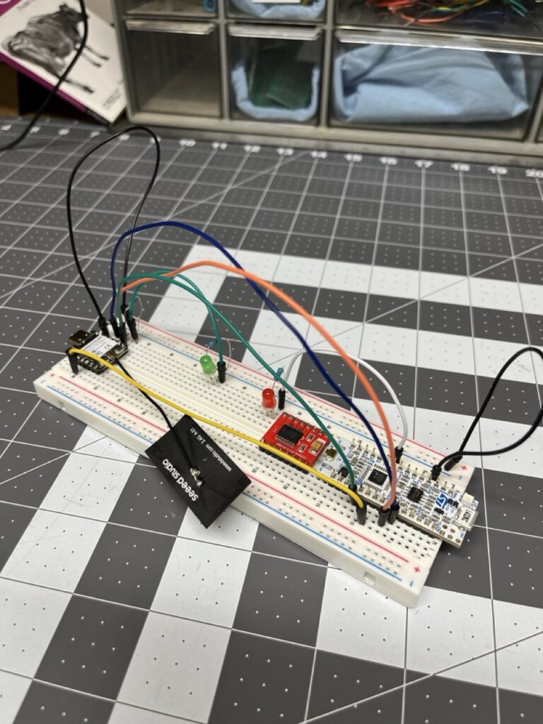
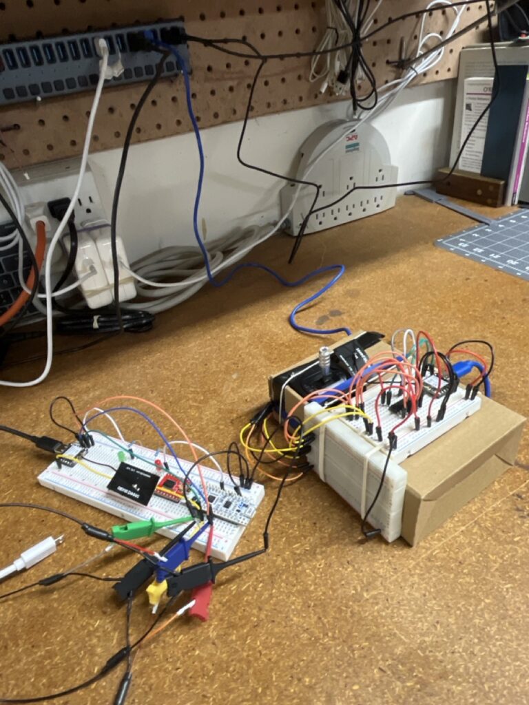
    System Architecture Overview

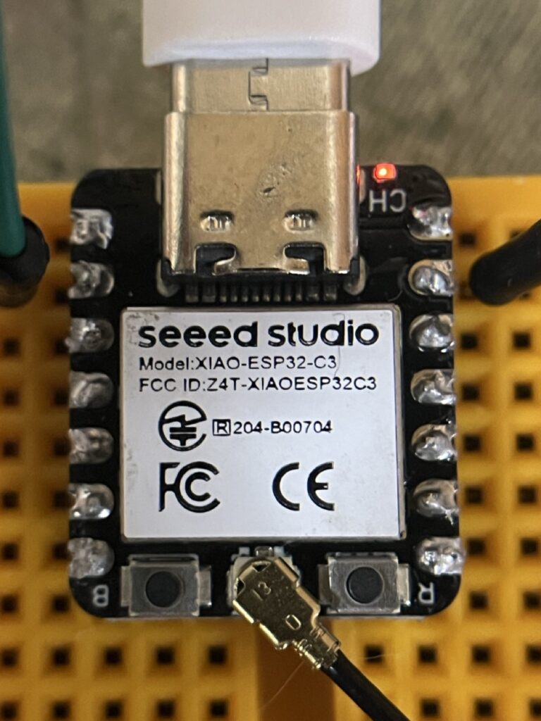
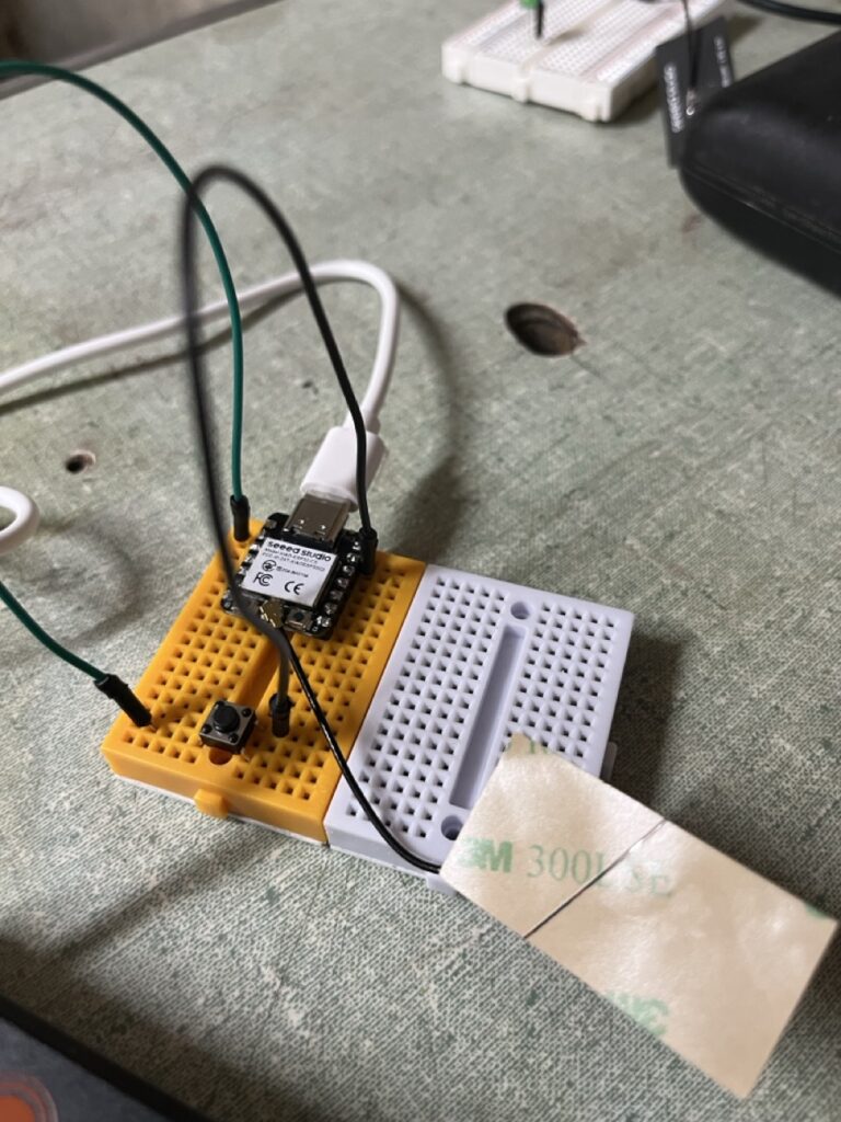
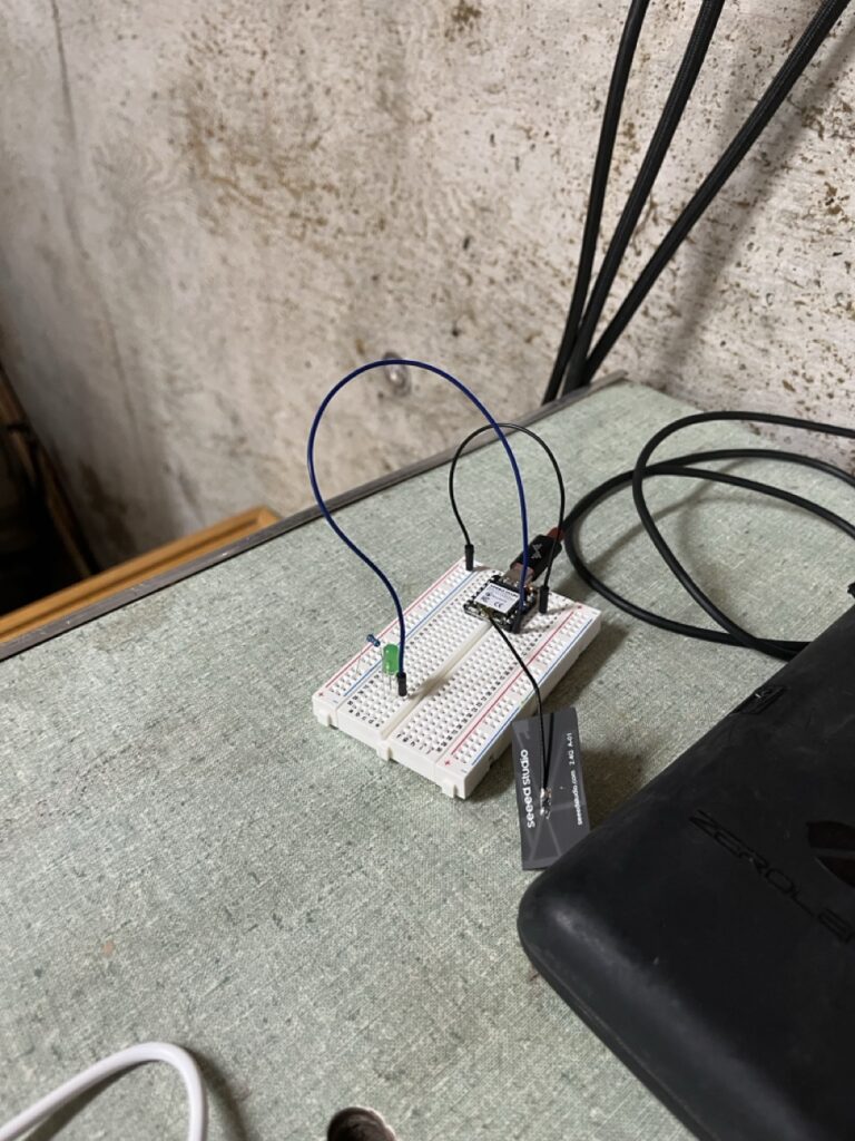
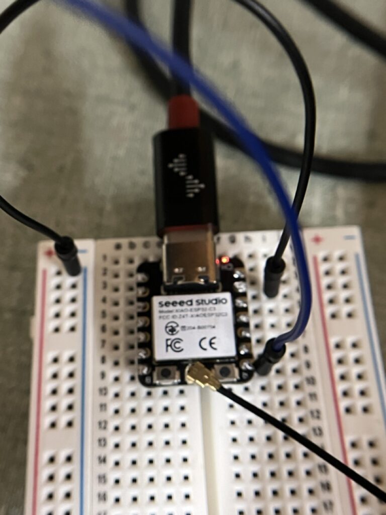
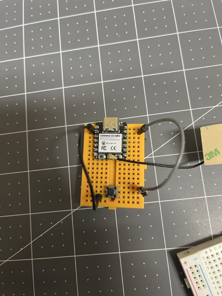
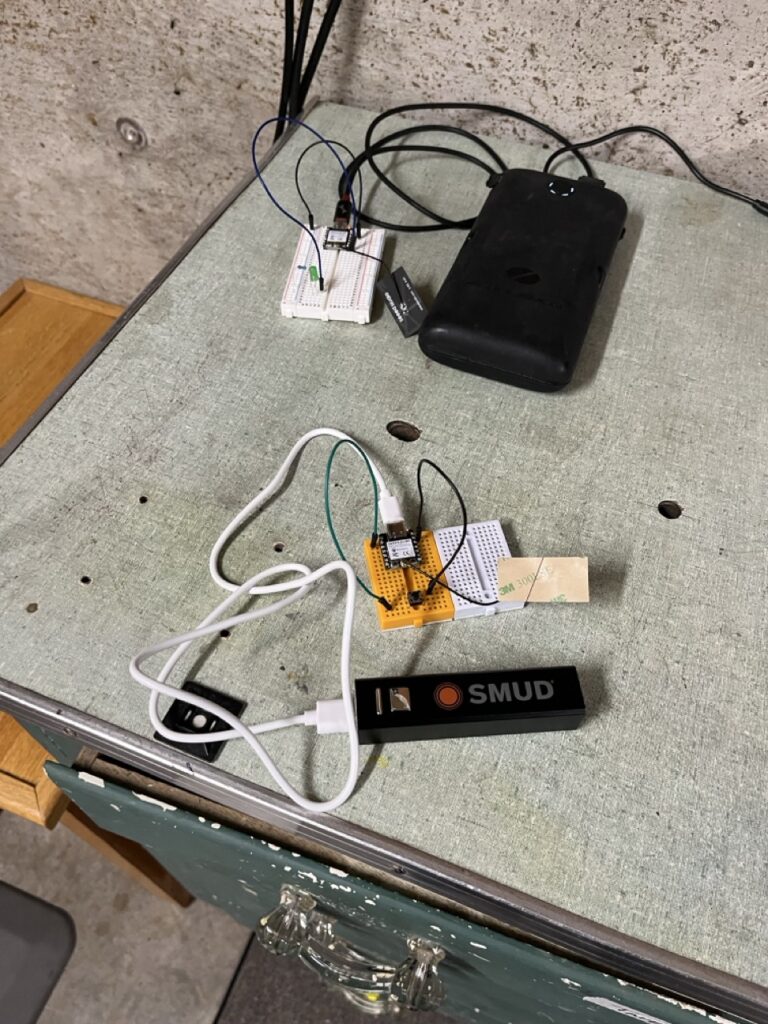
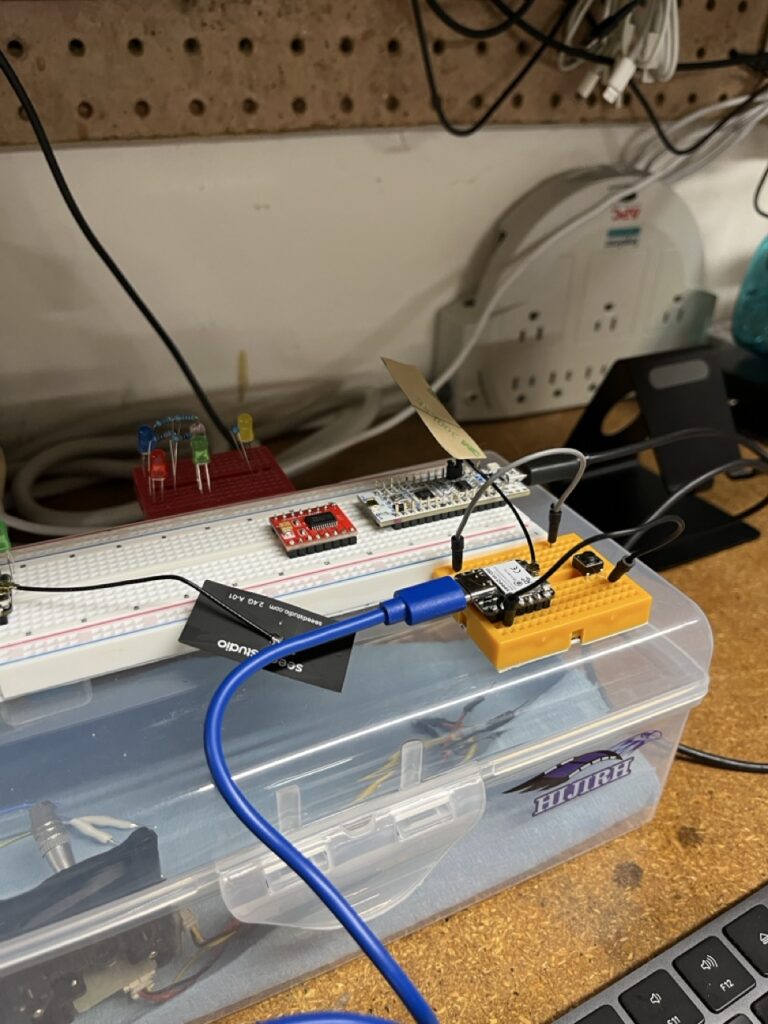
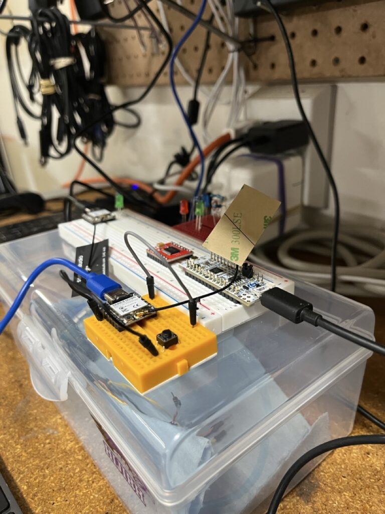
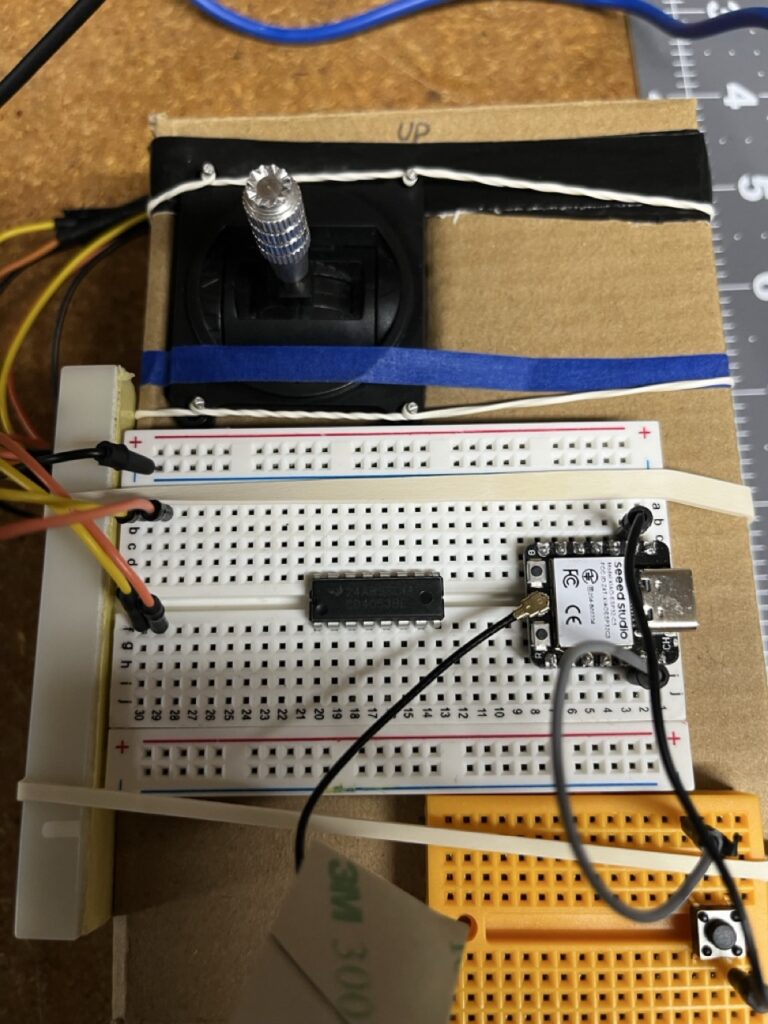
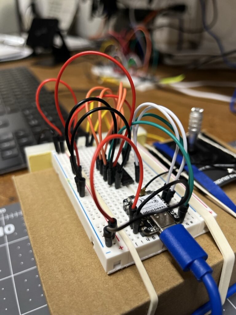
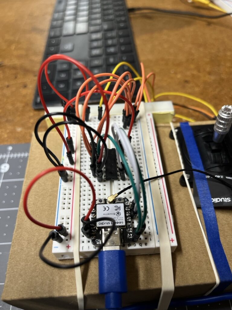
    Communication Layer: ESP32-C3 devices implementing ESP-NOW protocol 

    Motor Control: STM32L432KC with a TB6612FNG driver

    Interface Protocol: SPI with DMA for high-speed data transfer 

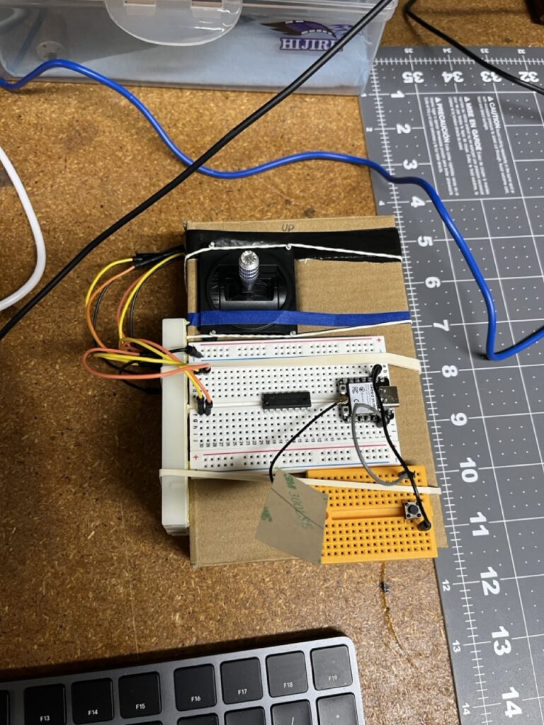
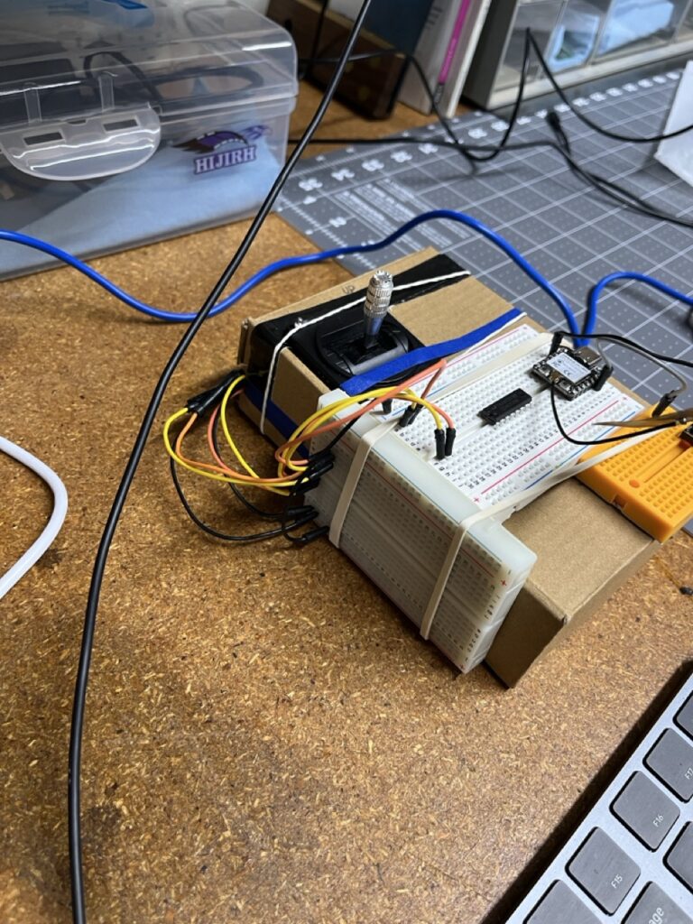
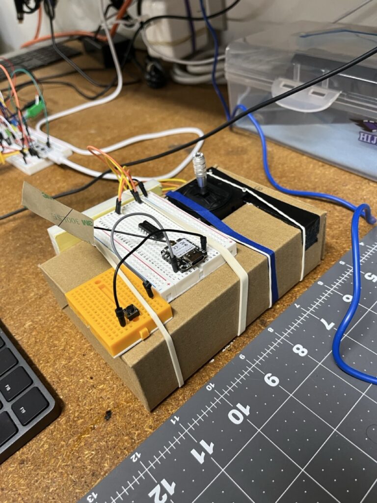
    Control Input: Analog joystick with multiplexed ADC expansion

    The rover represents three distinct engineering challenges operating as a unified system. Unlike previous projects that explored single concepts, this demanded mastery of wireless protocols, real-time motor control, and inter-processor communication simultaneously.

    The Technical Evolution

    From Simple to Complex Communication

    The communication system evolved from basic ESP-NOW message passing to sophisticated 12-bit ADC transmission. Early implementations sent simple command tokens (LIGHT_ONMOTOR_FORWARD) but rover control demanded continuous analog precision.

    ADC Resolution Challenge: Transmitting joystick positions as 12-bit values (0-4095) required careful attention to byte ordering and data integrity. ESP-NOW’s packet-based nature meant each transmission needed proper framing and error detection.

    Little Endian Encoding: ADC values split across byte boundaries demanded consistent endianness handling:

    c// Transmit 12-bit ADC as two bytes
    uint16_t adc_value = 2048;            // Mid-scale
    tx_data[0] = adc_value & 0xFF;        // LSB first
    tx_data[1] = (adc_value >> 8) & 0xFF; // MSB second

    Hardware Constraint Solutions

    ADC Limitation Discovery: The ESP32-C3 provides only 3 usable ADC pins, insufficient for dual joystick control (4 analog axes required). This constraint drove the implementation of analog multiplexing.

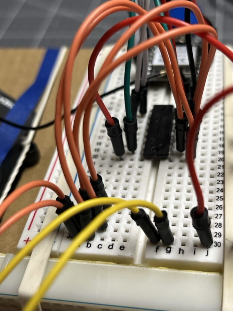
    CD4053BE Integration: The triple 2-channel analog multiplexer expanded 3 ADC inputs to 6, enabling complete joystick interface plus auxiliary sensor inputs. The multiplexer selection logic required precise timing coordination with ADC sampling.

    Multiplexer Control Sequence:

    1. Set digital select lines for desired channel
    2. Allow 10μs settling time for analog switching
    3. Trigger ADC conversion
    4. Store result with channel identification
    5. Advance to next channel

    This seemingly simple expansion revealed the importance of analog signal integrity and timing precision in embedded systems.

    Motor Control Board Architecture

    STM32L432KC Selection Rationale

    Processing Requirements: Motor control demands real-time response to changing input conditions. The STM32L432KC’s Cortex-M4 core with FPU provides computational headroom for control algorithms while maintaining deterministic timing.

    FreeRTOS Integration: Unified RTOS architecture between ESP32-C3 (native FreeRTOS) and STM32 (ported FreeRTOS) enables consistent multitasking patterns across the system.

    Development Workflow Optimization: Previous experience with STM32CubeIDE revealed workflow friction with existing VIM-based development patterns. The solution: STM32CubeMX for initial code generation, then integration into CMake-based builds.

    TB6612FNG Motor Driver

    Bidirectional Control: The TB6612FNG drives two motors with independent speed and direction control. The rover’s dual-motor configuration provides complete maneuverability with a single driver IC.

    PWM Speed Control: Motor speed regulation through STM32 timer-generated PWM signals. Frequency selection (1kHz) balances motor response with electromagnetic interference considerations.

    Current Sensing: Driver IC current feedback enables torque monitoring and stall detection for advanced control algorithms.

    SPI Communication Protocol

    Controller-Peripheral Architecture

    ESP32-C3 as Controller: The wireless receiver aggregates joystick data and system commands, then dispatches motor control updates via SPI.

    STM32 as Full-Duplex Peripheral: Motor control board responds to commands while simultaneously reporting motor status, current consumption, and sensor feedback.

    DMA Implementation Challenges

    Buffer Overflow Mitigation: Initial implementations suffered data corruption during high-frequency updates. DMA buffering resolved timing issues but introduced synchronization complexity.

    Packet Synchronization: Misaligned data reception required packet header implementation (0x1234 sync pattern) for reliable frame detection.

    Manual Chip Select Control: Hardware SPI /CS proved unreliable for packet boundaries. External interrupt (EXTI) control of chip select provided precise transaction timing.

    Engineering Methodology

    Iterative Development Approach

    Component Isolation: Each subsystem developed and validated independently before integration. ESP-NOW communication verified separately from motor control logic.

    Logic Analyzer Validation: Every protocol implementation validated with logic analyzer captures. Signal integrity problems invisible to software debugging became immediately apparent.

    Documentation Discipline: Real-time engineering journal maintained throughout development. Every design decision, failed approach, and breakthrough documented with sufficient detail for reproduction.

    Tool Integration

    Development Environment: VSCode with CMake for both ESP-IDF (ESP32-C3) and STM32 projects. Unified build system across heterogeneous targets.

    Debugging Infrastructure: OpenOCD and ARM GDB for STM32 debugging. ESP-IDF monitor for ESP32-C3 development. Logic analyzer for protocol verification.

    Version Control Strategy: Shared repository for the time being as I develop and build mastery in embedded systems.

    Current Status and Challenges

    Operational Achievements

    • ESP-NOW wireless communication established and stable
    • ADC multiplexing functional with 6-channel capability
    • STM32 motor control board responsive to SPI commands
    • Single motor driver operational with PWM speed control

    Active Development Areas

    SPI Protocol Refinement: Packet synchronization and error recovery mechanisms under development. Current focus on robust communication in electrically noisy motor control environment.

    Control Algorithm Implementation: Basic motor drive functional. Advanced features (acceleration limiting, coordinated turning, obstacle avoidance) planned for subsequent phases.

    System Integration Testing: Individual subsystems validated. Complete system integration testing in progress.

    Project Significance

    The Earth Rover represents a convergence of multiple embedded systems disciplines: wireless communication, real-time control, analog signal processing, and inter-processor protocols. Unlike tutorial projects that demonstrate single concepts, this system demands simultaneous mastery of diverse technologies.

    More importantly, it revealed how hardware constraints drive innovative solutions. The ESP32-C3’s ADC limitation led to multiplexer implementation, which sparked fascination with analog switching principles. This curiosity about fundamental logic operations ultimately catalyzed the DINO CPU project.

    Engineering Philosophy: Complex systems emerge from the disciplined integration of well-understood components. The rover’s success depends not on exotic technologies, but on meticulous attention to interfaces, timing, and signal integrity.

    The journey from simple ESP-NOW message passing to precision multi-axis motor control demonstrates how embedded systems engineering scales from basic communication to sophisticated control systems through methodical complexity building.

  • Bare-Metal Embedded C Programming: Understanding More

    Bare-Metal Embedded C Programming: Understanding More

    From Register Abstractions to Silicon Fundamentals

    After wrestling with the RP2040’s ROM assumptions and memory bootstrapping challenges in my OTA bootloader project, I realized something crucial: my embedded knowledge had significant gaps at the foundational level. While I could navigate Wi-Fi connectivity and JSON parsing for projects like PicoBook, the moment I needed to manually initialize runtime environments or understand what happens before main(), I was working with incomplete understanding.

    The OTA project’s failure wasn’t just about RP2040 quirks or Pico SDK assumptions. It exposed a broader truth about modern embedded development: HAL libraries and frameworks like Arduino, ESP-IDF, and STM32CubeIDE create powerful abstractions, but they can mask fundamental concepts until you need to step outside their boundaries. When you’re manually jumping between firmware partitions and reconstructing boot environments, those abstractions become obstacles rather than aids.

    Rather than continue building complex projects on shaky foundations, I made a strategic decision: master the fundamentals through deliberate study before launching my next major initiatives. I picked up “Bare-Metal Embedded C Programming” by Israel Gbati and committed to working through it systematically with an STM32F411RE development board.

    This wasn’t academic exercise for its own sake. I had The Earth Rover project on the horizon, which would require sophisticated motor control using an STM32L432KC, ESP32-C3 wireless communication, and precise SPI coordination between multiple microcontrollers. Having recently struggled with low-level memory management, I wanted to approach this complexity with genuine confidence rather than educated guessing.

    The learning journey proved transformative. Working directly with registers, implementing custom startup code, and understanding peripheral structures without HAL abstractions gave me the foundation to confidently use STM32CubeMX and CMake for The Earth Rover’s motor control board. More importantly, the book’s methodical approach to low-level programming ignited a deeper curiosity about computational fundamentals—pushing me even further down the abstraction stack to study how CPUs operate at the silicon level and explore the evolution of digital logic itself.

    What began as intentional knowledge building to understand embedded systems more deeply became a comprehensive foundation that now supports both my current Earth Rover development and my exploration of CPU-free digital logic in the DINO sequencer project. The goal was always to see where deeper understanding would lead, and it opened pathways I hadn’t anticipated when I first cracked open that book.

    The Learning Acceleration and Documentation Realization

    Working through the first nine chapters, I found myself moving faster than anticipated. The concepts were clicking, and I was refactoring code continuously rather than maintaining separate projects per chapter. What started as careful, methodical progress became an accelerated deep dive through GPIO control, timer implementation, USART communication, and SysTick integration – covering the fundamentals that would prove essential for complex multi-MCU projects.

    As I progressed through the more advanced peripherals—ADC configuration, external interrupts (EXTI), SPI communication, DMA transfers, and power management—I was exploring, implementing, and then refactoring without adequate documentation. The code worked, the concepts were understood, but the learning details were being lost in the rapid iteration.

    This realization marked a critical turning point in my engineering practice. I recognized that the complexity I was planning to tackle with The Earth Rover and DINO projects would require meticulous documentation, not just for others, but for future debugging and iteration cycles.

    Practical Application and Process Evolution

    The bare-metal experience provided the confidence to approach STM32CubeMX as a tool I understood rather than a black box I hoped would work. When configuring the STM32L432KC for The Earth Rover’s motor control board, I could evaluate the generated code against my register-level knowledge and make informed decisions about peripheral configurations.

    The accelerated learning process had taught me advanced peripheral concepts, but without proper documentation, those details were effectively lost. This gap led to a fundamental shift in my engineering practice: systematic documentation became non-negotiable. Both The Earth Rover and DINO projects now maintain detailed handwritten engineering journals, capturing every implementation challenge, design decision, and lesson learned—ensuring that hard-won knowledge doesn’t disappear in the next refactoring cycle.

    Transforming Engineering Approach

    Beyond specific technical skills, this deep dive fundamentally changed how I approach embedded challenges. Instead of pattern matching from online examples or hoping HAL abstractions work correctly, I now have the confidence to dig into datasheets and reference manuals when encountering unfamiliar territory.

    More significantly, understanding registers and peripherals at the silicon level sparked a curiosity about computational fundamentals that continues driving my learning. Questions about how CPUs themselves operate, how digital logic evolved, and what’s possible outside traditional microcontroller paradigms led directly to DINO’s CPU-free design exploration.

    The book’s methodical progression established a learning framework I now apply to every new technology: understand the fundamentals first, then build complexity systematically. Whether debugging SPI timing issues or designing address sequencing logic, the discipline of first-principles thinking has become central to my engineering approach.

    Sometimes the best way to build complex systems is to first master the fundamentals that make them possible.

  • Over The Air Update: An attempt

    Over The Air Update: An attempt

    How I tried, failed and dug deeper to get OTA proper without a library on the PicoW RP2040

    After the success of PicoBook, implementing Over-The-Air firmware updates seemed like the logical next step. Every deployed embedded device needs remote update capability, and the RP2040’s dual-core architecture with ample flash storage appeared well-suited for a dual-partition bootloader system.

    The goal was straightforward: build a minimal OTA system without external libraries, using only the Pico SDK. Firmware A (bootloader) would download new firmware images over Wi-Fi, write them to a reserved flash partition, and jump cleanly to the new code. Standard embedded practice, with existing reference implementations to guide the approach.

    What started as a weekend project became a three-week deep dive into RP2040 boot architecture, ARM Cortex-M initialization sequences, and the hidden assumptions buried within seemingly simple SDK functions. The project “failed” in that no working OTA system emerged, but succeeded in exposing fundamental knowledge gaps that would reshape my entire approach to embedded development.

    This documentation captures both the technical investigation process and the engineering insights that made every subsequent project possible.

    Initial Architecture & Approach

    The design followed standard embedded OTA patterns: a dual-partition system with clearly defined memory regions and responsibilities.

    Flash Layout:

    • Bootloader (Slot A): 0x100000000x10064000 (400KB)
    • Boot Flag Region: 0x100640000x10065000 (4KB)
    • Application Firmware (Slot B): 0x10065000 onwards (512KB+)

    Operational Flow:

    1. Bootloader checks boot flag and validates existing firmware
    2. If update required, downloads new firmware via Wi-Fi to Slot B
    3. Verifies download integrity and sets boot flag
    4. Performs manual jump to new firmware’s reset vector

    Jump Implementation Strategy:

    The critical transition from bootloader to application required setting up the ARM Cortex-M execution environment manually:

    uint32_t sp = *(uint32_t*)(app_base);    // Load stack pointer
    uint32_t entry = *(uint32_t*)(app_base + 4); // Load reset handler
    __asm volatile("msr msp, %0" :: "r"(sp));    // Set main stack pointer  
    *(volatile uint32_t*)0xE000ED08 = app_base;  // Update vector table offset
    ((void (*)())entry)(); // Jump to application

    This approach worked perfectly in theory and matched successful reference implementations. The bootloader compiled cleanly, established Wi-Fi connections, and successfully downloaded firmware binaries to the correct flash addresses.

    Early Success Indicators:

    • Clean compilation with proper linker script separation
    • Successful Wi-Fi connection and HTTP downloads
    • Verified flash writes at target addresses
    • Valid vector table generation in downloaded firmware

    The system appeared functional until the critical moment: jumping to the new firmware consistently triggered immediate HardFaults.

    The Hard Fault Investigation

    Initial Symptoms: Every jump to downloaded firmware triggered immediate HardFaults, despite valid vector tables and successful flash writes.

    GDB Trace Analysis:

    gdb
    #3  __aeabi_double_init ()
    #2  0x00000000 in ?? ()
    #1  <signal handler>
    #0  isr_hardfault ()

    The crash occurred during __aeabi_double_init(), specifically on this line:

    memcpy(&sd_table, rom_table_double, SF_TABLE_V2_SIZE);

    Key Discovery: rom_table_double pointed to 0x00000000 instead of valid ROM data.

    Memory Inspection Revealed:

    • (uint16_t*)0x18 = 0x0000 (should point to ROM function table)
    • (uint16_t*)0x1C = 0x0000 (should point to float dispatch table)
    • These pointers are only initialized during cold boot by the RP2040 ROM

    Root Cause: The Pico SDK assumes ROM-initialized state that doesn’t exist after manual firmware jumps. Cold boot initializes critical lookup tables; manual jumps bypass this entirely.

    Solutions Attempted

    Approach 1: ROM State Reconstruction – Based on reverse engineering the RP2040 boot sequence, I attempted to manually recreate the ROM’s initialization:

    c
    // Fake ROM boot environment before jump
    (uint16_t)0x18 = 0x001D; // rom_func_lookup pointer
    (uint16_t)0x1C = 0x024C; // rom_table_double pointer
    ((uint8_t)0x24A)[0] = 0x01; // Float table header ((uint8_t)0x24A)[1] = 0x40; // Table size (256 bytes)

    Approach 2: AEABI Function Table Initialization – The crash revealed that aeabi_mem_funcs[] was never populated. Manual initialization:

    c
    extern void *__wrap_memcpy(void *, const void *, unsigned); 
    *(uint32_t*)(0x20000270 + 4) = (uint32_t)&__wrap_memcpy;

    Approach 3: Link Register Safety – ARM functions expect valid return addresses in lr. Direct jumps leave it uninitialized:

    c
    // Trap value__asm volatile ("mov lr, %0" :: "r" (0xFFFFFFFF));  
    
    __attribute__((noreturn)) void (*app_entry)(void) = (void(*)(void))(reset_handler);

    Approach 4: Complete Runtime Bootstrap – Manual .data and .bss section initialization for the target firmware:

    c
    memcpy(&data_start, &data_load_start, data_size);
    memset(&bss_start, 0, bss_size);

    Partial Success: Each approach solved specific crash symptoms but revealed deeper dependencies. The 256-byte SRAM5 region, ROM lookup tables, and SDK initialization sequences formed an interconnected web of assumptions.

    The 256-Byte Discovery

    Critical Breakthrough: While investigating SRAM usage, I discovered the RP2040’s 256-byte secret.

    ROM Boot Sequence: The RP2040 ROM copies the first 256 bytes from flash (0x10000000) to SRAM5 (0x20040000), performs CRC verification, and executes it as the second-stage bootloader. This region remains accessible after boot.

    Live Memory Experiment:

    (gdb) x/64x 0x20040000 0x20040000: Valid structured code matching flash content 
    (gdb) set {unsigned int}0x20040000 = 0xdeadbeef 
    (gdb) x/8x 0x20040000 0x20040000: 0xdeadbeef # Memory is writable!

    Implications:

    • The ROM doesn’t lock this region after boot
    • SDK and firmware can read/write this memory
    • It contains the actual executed bootloader code
    • Could be used for persistent boot flags or metadata

    Engineering Insight: This discovery revealed how little I understood about the RP2040’s actual boot process. The datasheet mentioned the 256-byte region, but experiencing it live through GDB – seeing writable executable code in RAM – made the boot architecture tangible.

    Documentation Discipline: Each discovery was immediately documented with GDB commands, memory dumps, and hypothesis testing. This methodical approach became crucial as the investigation deepened.

    Reality Check: The project was no longer about implementing OTA updates. It had become an archaeology expedition into embedded system assumptions.

    Project Outcome & Learning Assessment

    Technical Result: No functional OTA system delivered after three weeks of intensive development.

    Engineering Value: Comprehensive understanding of RP2040 boot architecture, ARM Cortex-M initialization requirements, and embedded system dependency chains.

    Critical Realization: The gap between “SDK-guided development” and “bare-metal systems engineering” was far wider than anticipated. High-level APIs hide essential knowledge required for reliability-critical embedded systems.

    Knowledge Gaps Exposed:

    • ARM EABI calling conventions and runtime requirements
    • Memory section management (.data, .bss, .vectors)
    • Linker script behavior and symbol resolution
    • ROM-firmware interaction patterns
    • Assembly-level debugging techniques

    Methodology Validation: The systematic investigation approach – GDB traces, memory dumps, assembly analysis, datasheet correlation – proved essential for embedded debugging. Each tool revealed different aspects of the same complex problem.

    Trajectory Impact: This project fundamentally changed my approach to embedded development. The “failure” exposed the necessity of understanding systems from silicon behavior upward, not just API usage downward.

    Next Phase Catalyst: The investigation revealed that effective embedded engineering requires fluency in C, assembly, and hardware architecture. This directly motivated the transition to bare-metal development curriculum that followed.

    Conclusion

    This project exemplifies how the most valuable learning often emerges from apparent failures. What began as a straightforward OTA implementation became a masterclass in embedded systems architecture, revealing the intricate dependencies hidden beneath seemingly simple SDK functions.

    The investigation process – systematic debugging, documentation discipline, and willingness to dig deeper when initial approaches failed – proved more valuable than any working bootloader would have been. Understanding why the RP2040 behaves as it does, rather than just how to make it work, became the foundation for every subsequent project’s success.

    Key Takeaway: Embedded systems engineering requires understanding the full stack from silicon behavior to application logic. SDK abstractions are powerful tools, but they can’t substitute for fundamental knowledge when building reliability-critical systems.

    Technical Legacy: The debugging methodology, memory management insights, and ARM architecture knowledge gained here directly enabled the bare-metal C work that followed. The “failed” OTA project became the prerequisite for every successful project afterward.

    Return Intent

    This project will be revisited. The investigation revealed exactly what’s required – manual ROM state reconstruction, runtime bootstrapping, and careful memory management. The bare-metal curriculum that followed built the prerequisite knowledge to implement these solutions correctly. When resumed, this will demonstrate how foundational understanding transforms impossible complexity into systematic engineering.

    Engineering Philosophy: Sometimes the best projects are the ones that don’t work as intended but teach you everything you need to know for the next challenge.

  • The PicoBook

    The PicoBook

    The Gadget that started it all

    I wanted to build something that felt like a real product – not just blinking LEDs or hello world examples. A small, book-shaped device that could fetch and display content seemed like the perfect way to integrate multiple embedded concepts: wireless connectivity, display control, user interaction, and physical assembly.

    What I Built

    Wi-Fi connectivity: Connects to an EC2-hosted PHP API for messages.

    OLED Display: Renders JSON-parsed titles/authors with line wrapping and centering.

    On-demand fetch: A GPIO button triggers content refresh.

    Enclosure: Made from scored, folded, and cut plastic.

    Power: Runs via USB

    Hand-built: Fully hand-assembled and soldered.

    The Learning Journey

    Choosing MicroPython: I started with MicroPython because I wanted to focus on the system integration challenges rather than getting bogged down in low-level details. This turned out to be both a blessing and a limitation – while it let me build a complete working system quickly, it also left me feeling disconnected from what was actually happening at the hardware level.

    First Real I2C Experience: Getting the OLED display working taught me about I2C communication, pull-up resistors, and the importance of proper wiring. When things didn’t work, I had to learn to use a multimeter and logic analyzer to debug the communication.

    The Physical Reality: Building the enclosure by hand – scoring, cutting, and cementing plastic – made me realize how much engineering goes into making electronics practical and durable. It’s one thing to have a breadboard prototype; it’s another to create something that can survive being handled.

    What This Project Taught Me

    This project proved I could build complete embedded systems, but it also revealed my limitations. The MicroPython abstraction layer made me realize I wanted to understand what was happening closer to the hardware. This dissatisfaction with high-level abstractions became the driving force behind everything that followed – my dive into baremetal C, my attempts at bootloader development, and ultimately my decision to build a computer from discrete logic components.

    Technologies Used

    Microcontroller: Raspberry Pi Pico W

    Firmware: MicroPython

    Display: I2C OLED

    User input: GPIO button

    Enclosure: Hobby plastic, glue, knife

    Why This Project Mattered

    PicoBook wasn’t just my first embedded project – it was proof that I could take an idea from concept to working product. But more importantly, it showed me that I was more interested in understanding the fundamentals than just getting things to work. That realization shaped every project that followed.

  • Portfolio Launched

    Portfolio Launched

    Today marks the first commit and public launch of this embedded systems portfolio.

    The goal: document real hardware builds, experiments, and lessons learned—from concept to troubleshooting.

    Planned posts:

    • Upload a full write-up and documentation for PicoBook, a Wi-Fi connected OLED book display.
    • OTA Firmware Systems: Dual-partition bootloaders and over-the-air updates for RP2040, including deep dives into memory management and runtime bootstrapping.
    • Bare Metal Development: Custom startup code, linker scripts, register manipulation, and RTOS integration across STM32, ESP32, and RP2040 platforms.
    • DINO: A discrete logic CPU built from 74-series chips, fully manual from wiring to instruction set design.
    • The Earth Rover: A modular, wireless rover platform integrating STM32, ESP32, and real-time wireless control.

    Posts will be technical, thorough, and focused on practical insights and engineering details—covering everything from register-level programming to wireless protocol implementation.

    Check back soon for project breakdowns, build notes, and regular progress updates.