From Motor Control to Analog Input Reality
With STM32 integration providing reliable motor control communication architecture, the logical next step was replacing test data with real analog inputs from joystick potentiometers. This seemingly straightforward transition exposed a fundamental limitation that would reshape not only The Earth Rover project but spark an entirely new direction in digital logic exploration.
The ESP32-C3’s ADC constraints revealed themselves precisely when the project demanded more analog channels than the hardware could provide. This discovery initiated a chain of investigation that led from analog multiplexing solutions to discrete logic exploration, ultimately catalyzing the DINO CPU project.
The ADC Limitation Discovery
Initial rover control requirements seemed well within ESP32-C3 capabilities:
Required Analog Inputs:
- Left joystick X-axis (horizontal movement)
- Left joystick Y-axis (forward/backward movement)
- Right joystick X-axis (rotation control)
- Future expansion: Battery voltage monitoring
- Future expansion: Current sensing feedback
ESP32-C3 ADC Reality:
- ADC1: 5 channels available (GPIO0-GPIO4)
- ADC2: Shared with Wi-Fi functionality (unreliable during ESP-NOW operation)
- Effective channels: 3 reliable ADC inputs
The math was unforgiving: 5 required inputs, 3 available channels.
Initial Workaround Attempts
Channel Sharing Investigation: Testing revealed ADC2 interference with ESP-NOW communication, making Wi-Fi and additional ADC channels mutually exclusive.
External ADC Evaluation: Adding dedicated ADC chips (MCP3008, ADS1115) introduced I2C/SPI complexity and additional component costs.
Redesign Considerations: Moving to ESP32-S3 would solve the ADC problem but require complete firmware architecture changes.
None of these approaches felt elegant for a project focused on understanding embedded fundamentals rather than simply achieving functional goals.
The CD4053BE Discovery
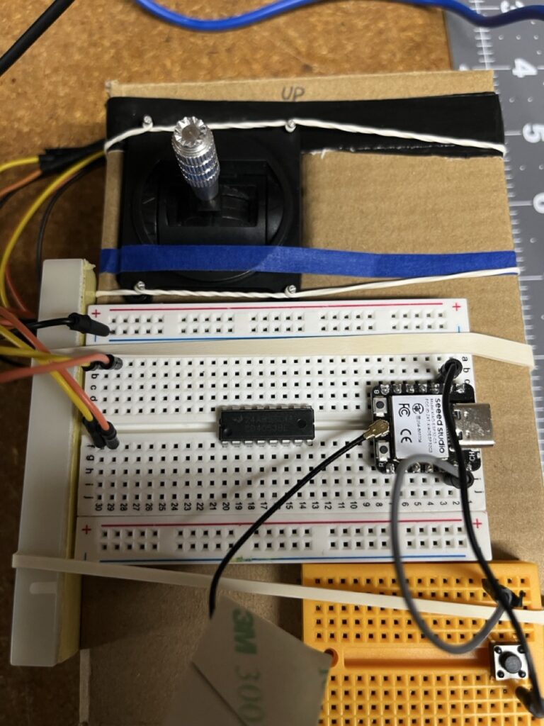
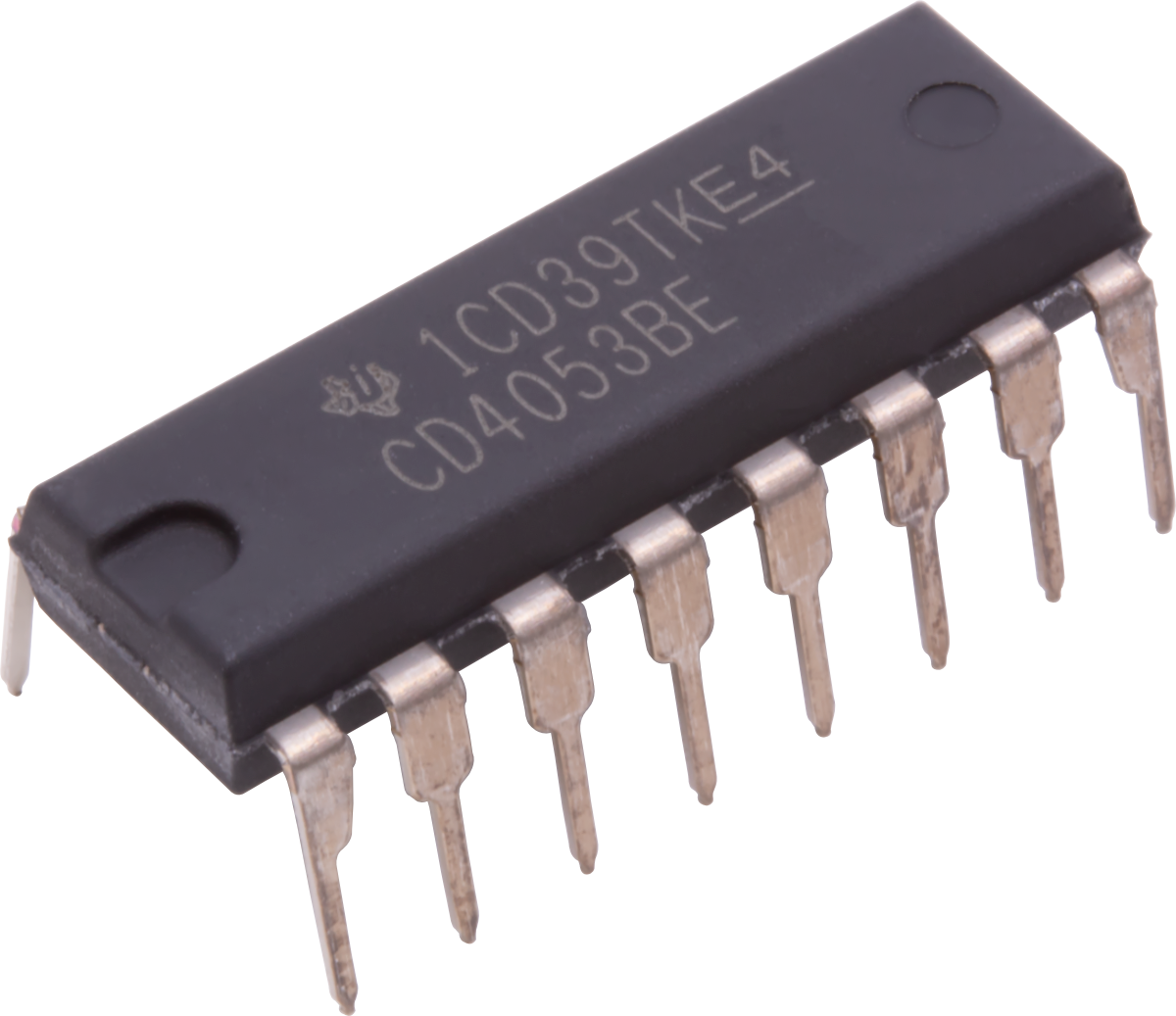
Research into analog signal routing led to analog multiplexers, specifically the CD4053BE triple 2-to-1 analog switch.
CD4053BE Characteristics
Component: CD4053BE Triple 2-to-1 Analog Multiplexer Function: Routes analog signals based on digital control inputs Key Specifications:
- Three independent 2-to-1 switches
- 5V operation compatible with ESP32-C3
- Low on-resistance (80Ω typical)
- Control via digital GPIO pins
Multiplexer Implementation Investigation
The CD4053BE enabled potential ADC expansion through time-division multiplexing concepts. Research focused on understanding how analog multiplexing could address the channel limitation while maintaining signal integrity.
Channel Expansion Potential
With three CD4053BE multiplexers, the ADC capability could expand significantly:
Original: 3 ADC channels With Multiplexing: 6 ADC channels (3 × 2-to-1 switching) Future Scalability: 12+ channels possible with additional multiplexers
This solution offered the analog input capacity needed for comprehensive rover control while introducing minimal complexity.
KiCAD and Wiring Diagram Necessity
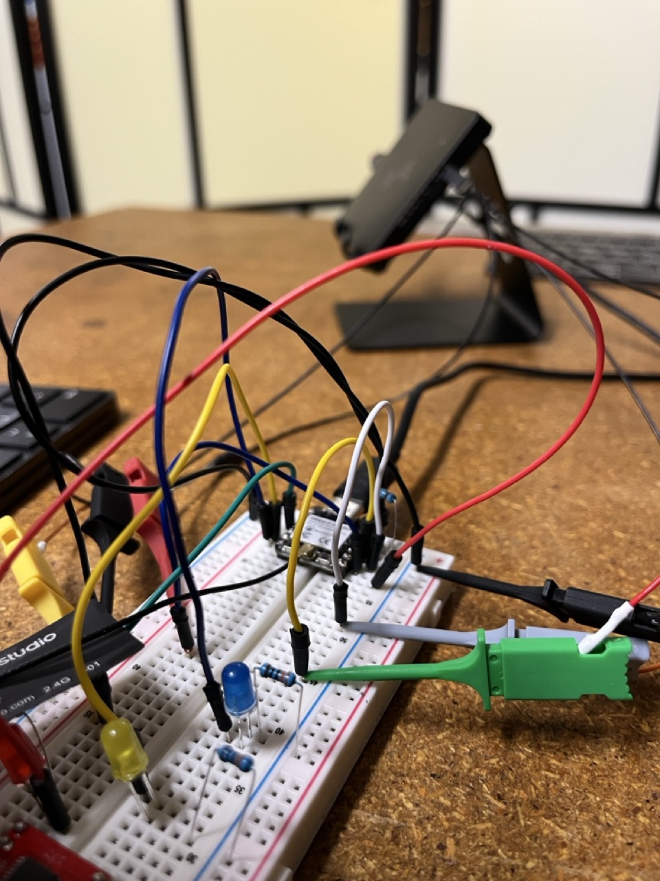
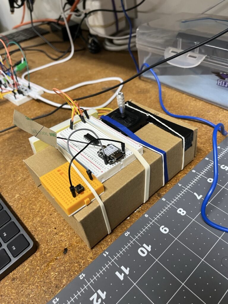
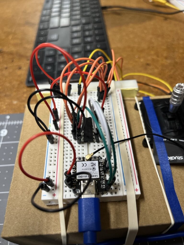
The multiplexer integration revealed the inadequacy of breadboard prototyping for documenting and maintaining complex analog circuits.
Circuit Complexity Growth
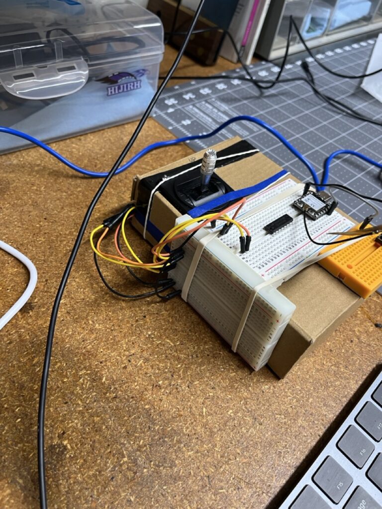
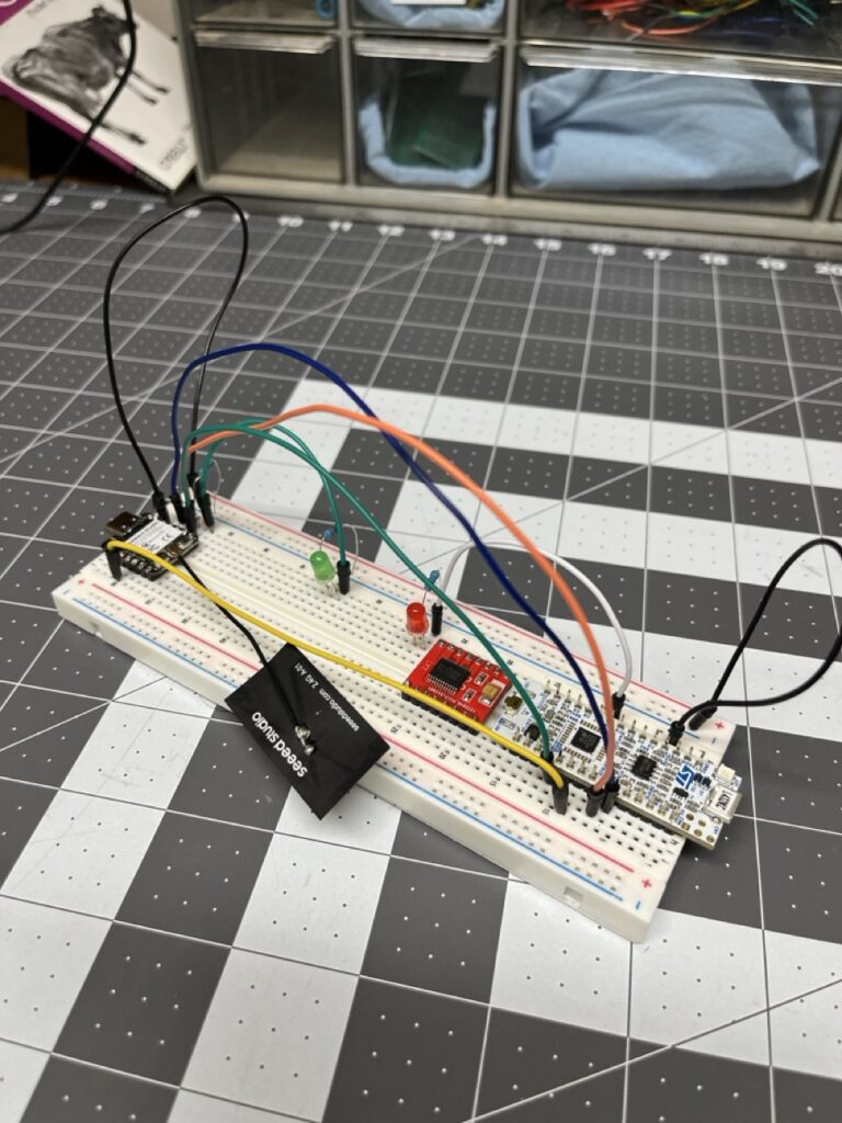
Component Count Increase:
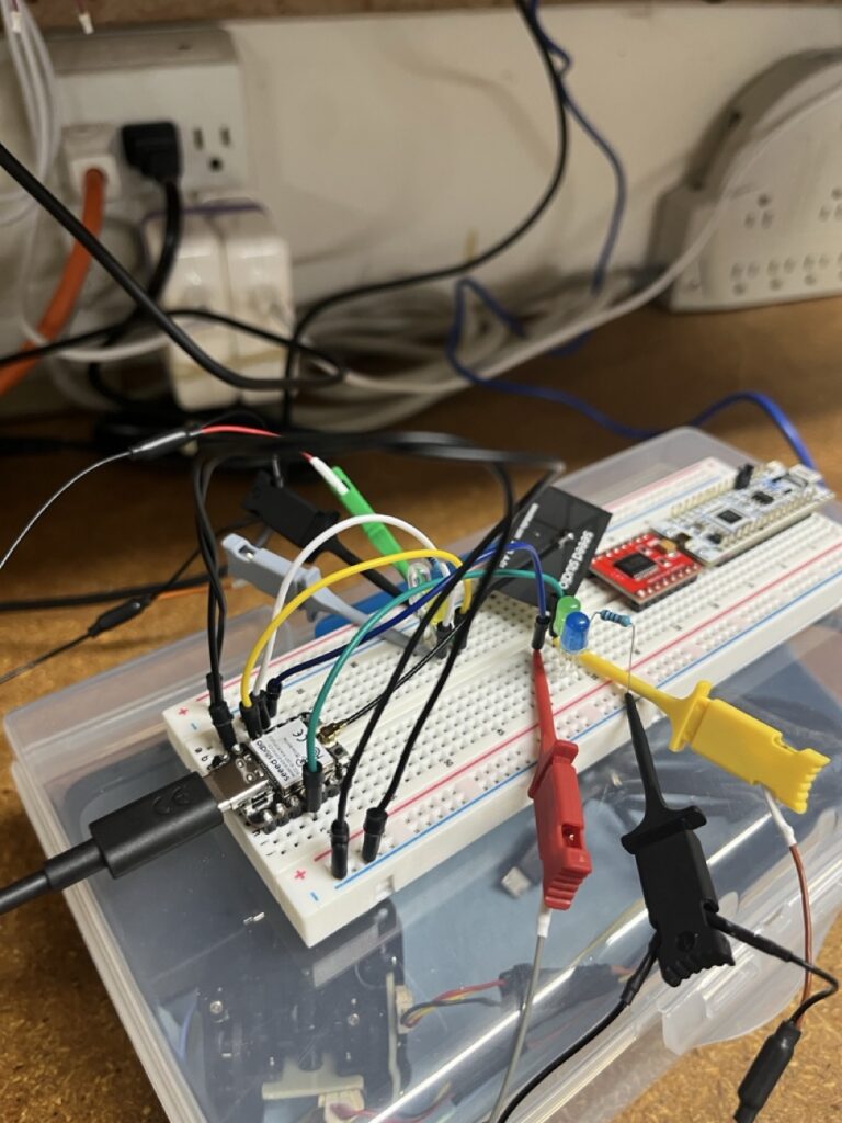
- ESP32-C3 controller
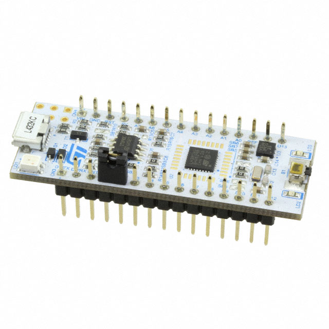
- STM32L432KC motor control board
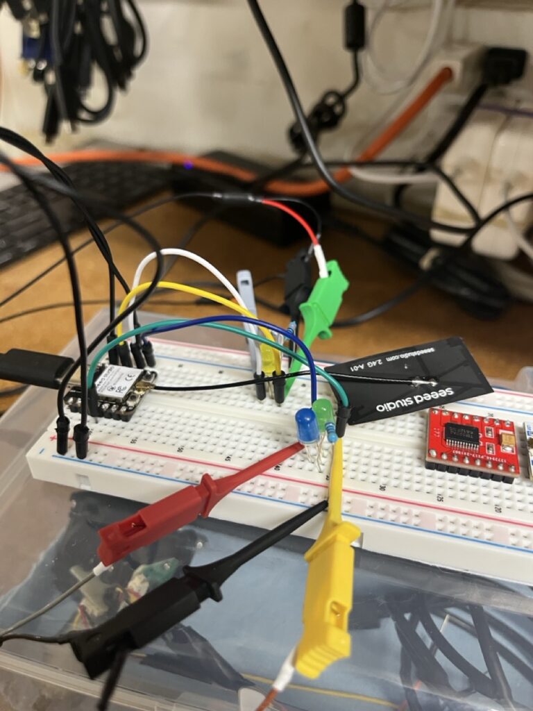
- Three CD4053BE multiplexers
- Joystick potentiometers (multiple axes)
- Power distribution and filtering
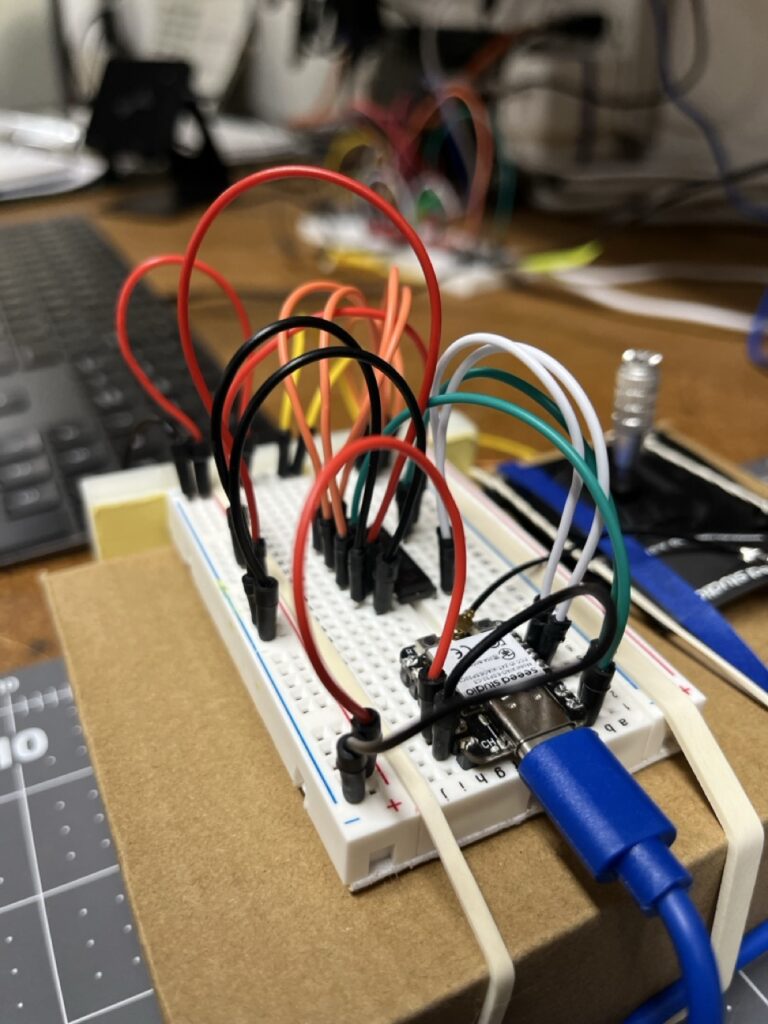
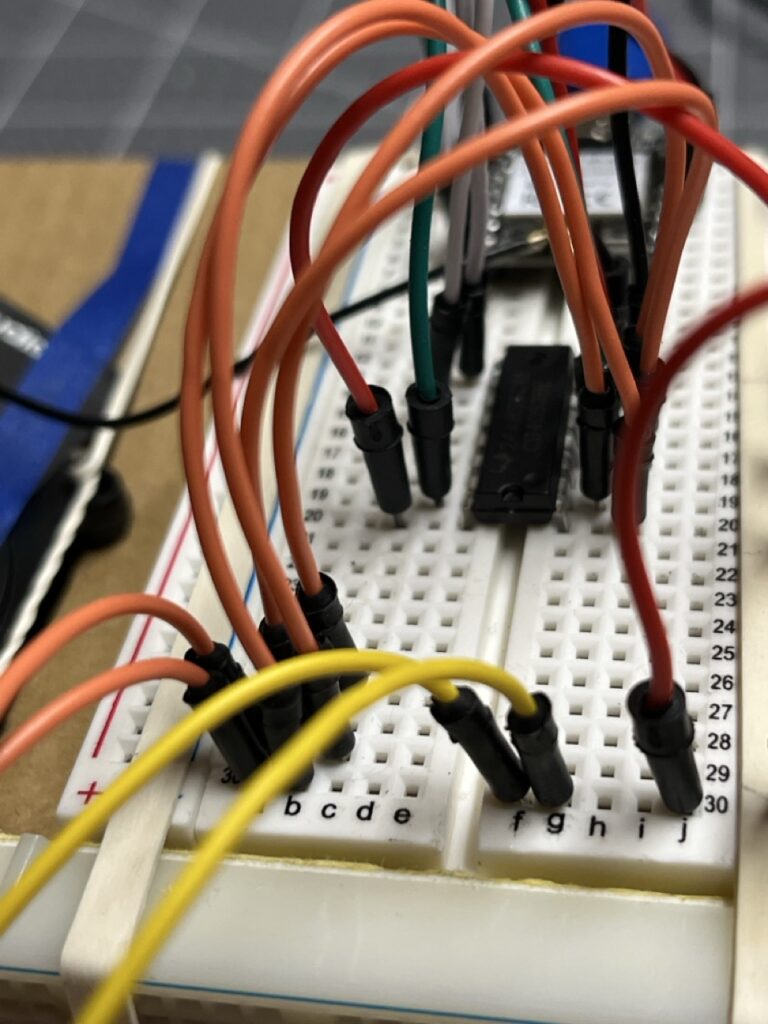
Wiring Complexity:
- ADC signal routing through multiplexers
- Digital control lines for MUX selection
- Power distribution for multiple voltage domains
- SPI communication between controllers
KiCAD Learning Integration
Schematic Capture: Creating formal circuit diagrams for reproducible builds Component Library Management: Establishing standardized symbols for project components Net Management: Tracking signal routing across complex multi-board systems Documentation Standards: Generating professional-quality circuit documentation
Engineering Insight: Complex embedded projects require formal circuit documentation for debugging, reproduction, and future modification. Breadboard sketches become inadequate quickly.
The Endianness Resolution
Successful analog multiplexing implementation required resolving data format consistency across the entire TX→RX→MCB communication chain.
Multi-Platform Data Consistency
ESP32-C3 ADC Data: 12-bit values in little-endian format ESP-NOW Transmission: Network byte order considerations STM32 Reception: ARM Cortex-M little-endian native format
Protocol Development
Establishing consistent data representation became critical for reliable multi-platform communication. The investigation focused on creating standardized data formats that would work reliably across ESP32-C3, ESP-NOW, and STM32 platforms.
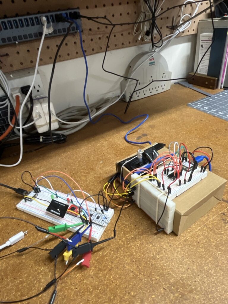
Integration Milestone Achievement
The successful completion of analog multiplexing investigation marked a critical project milestone:
Technical Understanding Achieved
- ADC Expansion Strategy: 3 channels expandable to 6+ through analog multiplexing
- Real Analog Input Planning: Joystick potentiometers ready to replace test data throughout system
- Multi-Platform Data Consistency: Reliable data format standards across ESP32-C3, ESP-NOW, and STM32
- Circuit Documentation Framework: Formal KiCAD schematics for reproducible construction
- System Integration Readiness: Complete TX→RX→MCB chain prepared for real sensor inputs
The DINO Catalyst
The CD4053BE multiplexer investigation had an unexpected consequence: it sparked fascination with discrete logic components and their capabilities.
Digital Logic Curiosity
Working with the CD4053BE raised fundamental questions:
- How do analog switches work at the transistor level?
- What other logic functions can be implemented with discrete components?
- Could complex digital systems be built without microcontrollers?
Historical Computing Interest
The multiplexer research led to exploration of historical computing architectures:
- How were computers built before microprocessors?
- What logic was possible with TTL and CMOS components?
- Could a complete CPU be constructed from discrete logic?
DINO Project Genesis
These questions catalyzed the DINO (Discrete INtegrated Operations) CPU project – an exploration of building computational systems using only discrete logic components, no microcontrollers.
Key Realization: The same problem-solving approach used for analog multiplexing could be applied to digital logic design. Sequential circuits, memory systems, and arithmetic operations were all achievable with discrete components.
Engineering Philosophy: Understanding computational fundamentals by building them from first principles, just as the bare-metal C programming had revealed embedded system foundations.
Project Trajectory Transformation
The successful Earth Rover ADC expansion investigation created an unexpected fork in the development path:
Rover Development Continuation
With analog input strategy established, The Earth Rover project could continue toward:
- Enhanced control algorithms
- Autonomous navigation features
- Remote monitoring capabilities
- Advanced sensor integration
DINO Project Initiation
Simultaneously, the discrete logic curiosity sparked an entirely new project direction:
- CPU-free digital logic exploration
- Sequential circuit design with discrete components
- Memory systems built from TTL/CMOS logic
- Eventually: complete 8-bit CPU construction
Engineering Decision: Rather than choosing between projects, both would proceed in parallel, with rover development providing practical embedded experience while DINO explored computational fundamentals.
Methodology Evolution
The ADC expansion phase refined several critical engineering practices:
Component Research Depth
Beyond Specifications: Understanding not just what components do, but how they enable system-level capabilities Alternative Solution Evaluation: Systematic comparison of different approaches before implementation Scalability Consideration: Choosing solutions that support future expansion rather than minimum viable implementations
Documentation Standards
Formal Circuit Documentation: KiCAD schematics as first-class project deliverables Integration Testing Protocols: Systematic validation procedures for multi-component systems Decision Rationale Recording: Documenting why specific approaches were chosen for future reference
Learning Transfer
Cross-Project Knowledge Application: Multiplexer investigation techniques transferring to discrete logic exploration Fundamental Principles Focus: Understanding underlying concepts rather than memorizing specific implementations Question-Driven Investigation: Allowing curiosity about component behavior to drive deeper technical exploration
Looking Forward: Parallel Development Paths
The successful ADC expansion milestone established two parallel development trajectories:
Earth Rover Evolution
Continued development of the rover platform with enhanced capabilities:
- Advanced control algorithms using expanded analog inputs
- Autonomous navigation feature development
- Remote monitoring and telemetry systems
- Integration with additional sensor modalities
DINO Project Launch
Exploration of discrete logic computational systems:
- Basic sequential circuit design and implementation
- Memory system construction from discrete components
- Arithmetic logic unit development
- Eventually: complete CPU architecture implementation
Unified Approach: Both projects would share the same methodical engineering approach, systematic documentation practices, and fundamental understanding focus that had proven successful throughout the rover development.
Key Insight: Sometimes the most valuable project outcomes are the unexpected directions they reveal. The ADC expansion investigation solved an immediate technical problem while opening entirely new avenues for exploration and learning.